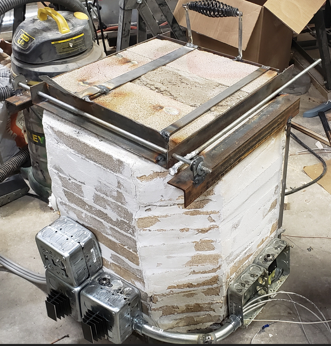
Alright, after half a dozen burnt out coils it’s time to head in a new direction. The problem is the more current the coil can handle the more the resistance drops. It’s an endless game of chasing my tail. So here’s what were going to do.
Bipolar Junction Transistor
or BJT is possibly the answer. Everyone is probably familiar with or at very least aware of transistors. They’re basically a relay and when you combine a few trillion of them you get a PC. A BJT is a little different. It is an amplifying transistor. Basically what that means is the more current you supply to the control pin the higher the amperage passed through climbs. I believe these are the core component in audio amplifiers and things like that.
How does this help us? Well the other product of this function is current limiting. These transistors have a current rating and a current limit cap.
So what we will do is use a BJT (mouser.com this one in fact) which has a cap of 40 amps and a voltage rating far above what we’re going to need in conjunction with some 14 awg nichome wire. Yes I know 14 awg isn’t meant to carry that much current but I think it will hold, we want it to get hot anyway right? This setup will limit our current to 40 amps through our 14 gauge wire and hopefully it will get really really hot without melting.
What if it doesn’t work
Well if it doesn’t work I have one more plan up my sleeve, maybe two. The other thing we can do with the BJT is limit the current based on the nichrome coil’s temperature. We can feed an analog signal to the BJT from the nodeMCU (esp8266\arduino) and regulate how much current is supplied based on a sensor on the coil itself. The one really tricky part with this is getting another thermocouple into the heating chamber, I really don’t want to put any more holes into the smelter. Also we need a thermocouple that can handle the temperature and that coil needs to get hotter than the max temp of the smelter to be able to get the smelter to that temp, 1200F or something like that.
One final option will be to set up PWM (pulse width modulation) on the SSR (solid state relay) control pin from the nodeMCU. This would basically energize the coil only part of the time (over the span of 80hz or maybe 40hz, these nodeMCUs are definitely knockoffs) in theory preventing the coil from getting too hot and melting. The biggest problem with this is the SSRs, in my experience, can’t switch fast enough to handle true PWM and usually just do nothing, the Base never becoming fully saturated before the control signal is switched off. We would have to overcome this by creating ultra slow software PWM in our code, which isn’t a big deal really.
See You Later!
Expect an update on this soon. I really need to get this thing going, I’m drowning in projects and I can’t afford to have one linger this long.
Subscribe below so you don’t miss any updates and check back in a couple hours, I’m just about to post the next project were working on. Is it weird I find the sound of a 3D printer in the background soothing while I write?

