
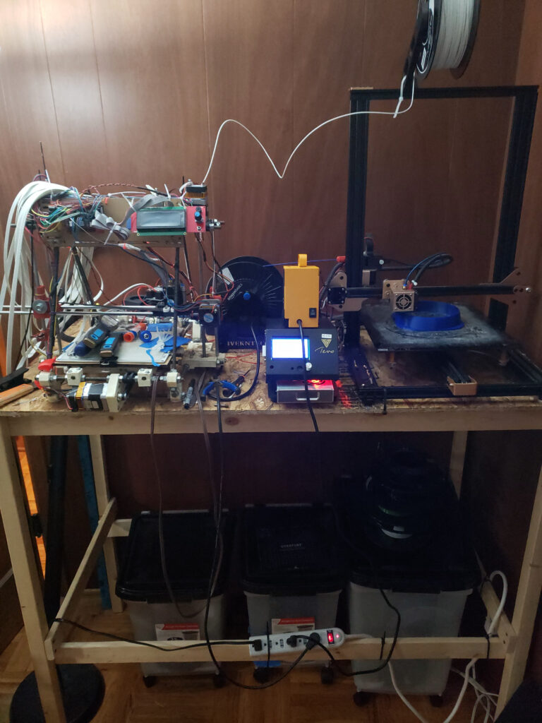
I am a big fan of 3D printing as you can see above. I’ve been involved with 3D printing for something like 14 or 15 years. You can see my RepRap Mendel in the pic next to an lightly modified Tevo Tornado. Of course the RepRap has modern electronics, ramps 1.4 I think and a slightly redesigned carriage and an E3D hot end. Man those original hot ends were a chore, nichrome wire wrapped around super expensive one off nozzles with the whole thing wrapped in kapton. What a mess, it’s amazing the whole thing went anywhere. Especially considering the cost. I remember paying $50 per stepper driver. Just those boards cost more than that Tevo.
Anyway, 3D printing has become one of the most valuable tools I have at my disposal. I’m constantly thinking up new things to do with my printers and prototyping new parts on them. That said, I also seem to run into the limitations of the printers often. The build volume is an obvious limitation but also the materials I can effectively print is an issue.
I want to be able to produce perfect parts in carbon fiber reinforced polycarbonate and I want to be able to print a 2 foot cube of it if that’s what I need. And I want to be able to print FAST, like really really fast.
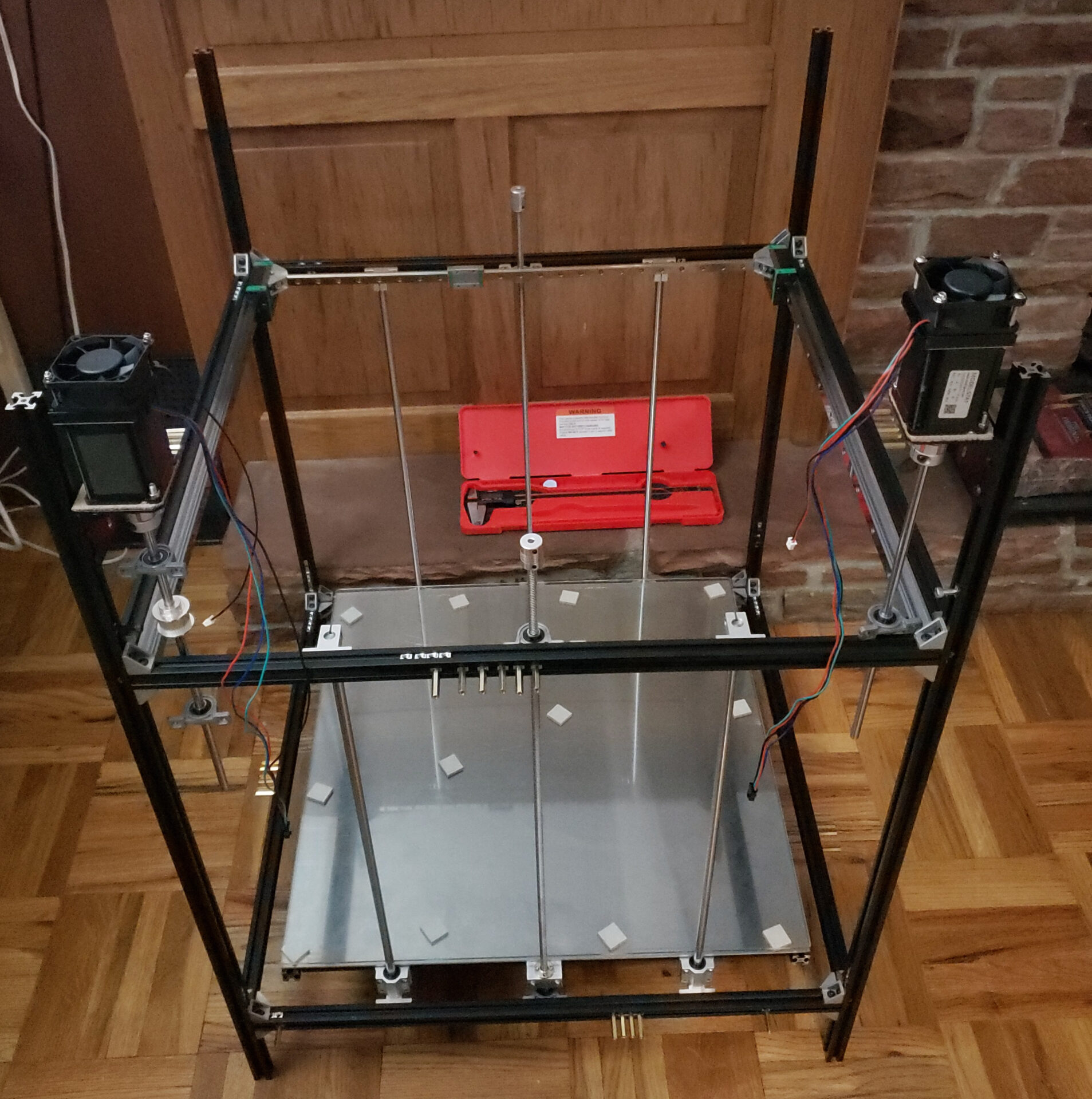
So here it is. I call it the Big Boy. You can see the 12 inch digital caliper case behind the machine there for scale. That’s about a 2 cubic foot build volume. If you know a bit about 3D printing you might be thinking 2020 aluminum extrusion is not up to this challenge, it’s not rigid enough. Not to worry, I have a plan. But first some details.
The Details
So you can probably tell this is going to be a CoreXY machine. That means the carriage rail runs on its own set of rails (basically). Some of the biggest speed issues I’ve come across are the result of the very heavy print bed slinging back and forth, not to mention the belt slipping and throwing of your layer. The best way I’ve seen to mitigate this is with a CoreXY printer. The bed remains stationary, other than vertical movement, and the hot end and its rail are the only parts that move on a single layer. The mass of this is drastically lower meaning it can move faster with less inertia to compensate for.
I considered building it on its side for this same reason. If you were to make the carriage rail parallel to the ground and add a counter weight system the carriage, hot end, and rail would basically have zero inertia. Unfortunately I don’t want relocate this challenge to bed adhesion, especially considering one of the main functions of this printer is going to be exotic materials.
Exotic Materials
One of top ranking features I want is to be able to print basically anything, as long as its classified as a thermoplastic. I want to print carbon fiber reinforced polycarbonate, and nylon, and peek, and ASA, and PVC, and whatever other kind of non-sense I can find.
There’s two main issues here. First off a lot of, if not all of, these chemicals release fumes that will potentially kill you. Unfortunately according to my figures that will result in significantly fewer prints from this machine so it must be mitigated. And I have a solution but first the second problem.
The other issue with these materials is most of them are prone to insane warping. Warping to the point where you aren’t getting a usable print without serious compensation. The solution to both is the same.
Solution 1
We’re going to enclose this thing completely. Not just enclose either but insulate, heavily. This is basically going to be a giant oven capable of 100c ambient temperature. With the printing chamber thoroughly enclosed we can also add a vent system to allow the fumes to be piped wherever necessary. You might have noticed from the picture this thing is in my office right now. Conveniently it is next to my fireplace (yeah I have a 10 foot stone wall with a fireplace in it in my office, see my upcoming articles about succeeded in the work place if you have an issue with that) and I considered piping this out the chimney however I came to the conclusion this was still too dangerous in the house.
Did you know melting PVC can release chlorine gas? Good luck with that. So we will actually be installing this in the shop, near the 24 inch exhaust fan.
Next Problem
So the next obvious question is “won’t 100c destroy all the electronics and motors and everything?”. Well in normal circumstances, yes, definitely. We have a solution for that as well. You might have noticed the two giant (nema 23) stepper motors mounted on the frame that exceeds well above the print chamber. The verticals extend that far because that is going to be the electronics chamber. The frame below will be the internal edge of the enclosure and there will be significant mineral wool insulation between the two chambers. The driveshafts that extend down into the print chamber will operate the X and Y axes after passing through the insulation.
You might be wondering why no one has done that on current off-the-shelf printers. Well unfortunately that’s simple some company that sells half-million dollar 3D printers patented the concept so no consumer printer manufacturer could utilize the design. It’s a really good example of patent over-reach as well. The concept of enclosing the printer with the electronics external is prohibited. That’s not proprietary or trade secret bub, it’s pretty obvious. Patent clerks are lazy or at least preoccupied with their physics problems. I do believe that patent expired somewhat recently though so maybe we’ll start seeing this obvious design.
Speeeeeeeeeeeeeeed
Ok so how are we going to get truly silly speeds.
Well rigidity is a concern. Remember earlier when I said I had a solution for that? See the little brass standoffs dotted all over the outside of the printer frame? Those are the mounting points for the printer enclosure. This will be made of galvanized steel flashing (it’s actually used for the eaves of your house, check it out at your local hardware store, cheapest source for sheet metal I’ve been able to find) and it will be affixed in big sheets to the outside of the frame at many points. This will add massive rigidity to the printer. Picture trying to stretch a piece of sheet steel by pulling on the edges.
Next up some physics. The faster something travels the more energy it contains. The more mass the object has the more energy it has. Now multiply the two. Even though I used a very light linear rail for the carriage and I have a super light weight carriage designed as well as plans for a Bowden tube system we’re still talking a couple pounds. At 90mm per second that’s about 0.004 joules or 0.566 in/oz. The max output of a standard nema17 stepper motor is something like 18.4 in/oz. So we need to overcome that and then also accelerate on top of it. These figures add up fast as well.
So the easy way out it is, nice big fast nema 23 motors which deliver nearly 200 in/oz. That should have no issue with this ask. But it raises another problem. I want to use mostly standard control electronics. That means ramps stepper drivers. I also want all those cool new features like lost step detection and software endstops, etc. Can we do it? You bet your buttcheeks we can.
Have a look at the BIGTREETECK TMC5160. Max drive current 4.4A. Our Nema 23 steppers only need 2.3. We should have UNLIMITED POWER.
More Power More Problems
So we should be able to run that carriage assembly so fast it will flip the printer over. This brings us to the next issue. I like Marlin, I like Marlin a lot. I like the community, I like the firmware, I’ve been using it for years. Unless something has changed Marlin printer firmware does not support resonance tuning. Unfortunately this means we need a change.
Clipper
If you’re into printing you’ve probably heard of clipper. You’ve also probably heard of that German fellow, Thomas Salamander Saladfinger Stratocaster Sanladerer. From his account the clipper community well make you prefer Marlin. Unfortunately I need resonance tuning. If you aren’t familiar with the system basically you stick an accelerometer on your printer and tell it to tune itself. It will start shaking and shimmying until it finds the particular resonance frequencies that will rattle your printer to pieces or possibly just make it relocate to the opposite end of the room. Then it makes the firmware avoid these harmonics. The faster your printer runs the worse this problem will be.
If I wanted to I could sink anchors into the shop’s concrete floor and bolt this thing down but it would still have a real chance of rattling itself apart. This tuning is the only effective way I see to prevent this. It can also cause other issues that impact your print causing waves and various shifting harmonic based things.
So clipper it is.
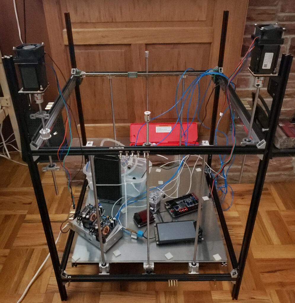
This presents another issue I don’t care for. Clipper doesn’t run on your printer controller board. You might have noticed a BIGTREETECH Octopus and BIGTREETECH TFT70 7 inch touchscreen on the build platform in the picture. That’s pretty much top of the line hardware with a price tag that reflects it. That is all more or less useless for this printer. I was planning on using Marlin when I bought it but I’ve been working on this for maybe 4 years and I don’t think clipper or resonance tuning was a thing back then.
Clipper runs on a Raspberry Pi which then talks to a super basic firmware that runs on your controller to run the printer. I’m probably going to put it on a ridiculously overpowered VM on one of my servers if I can though. I do intend to set up OctoPi as well though for all its cool features so we’ll see.
More Speed More Problems
Alright, the next issue I’ve run into with my printers and speed is just the speed at which plastic melts. I have an E3D Volcano hotend in the Tevo with a Bondtech CHT nozzle. The bottleneck I have hit is still just how fast I can push plastic through that nozzle. Even PLA at 250C with that rig and a 0.6mm nozzle and I still capped out on plastic.
So what to do? I.. have… a…. PLAN….
From my research Diamond nozzles have the highest thermal conductivity of any material. Bonus factor, we’re going to be running the nastiest filaments they makes so brass would disintegrate in moments. So we’re going to use a 0.8 Diamondback Nozzle for only $100. But that won’t get is where we’re going along.
We’re also using an E3D Super Volcano hotend. According to E3D that hotend outputs more than twice the volume of the standard Volcano and only costs a bunch more money. But wait… do they make a super volcano diamondback nozzle? They sure don’t.
But that’s not a bug, that’s a feature. We’re not even using a standard volcano diamond nozzle, which I think does exist. Remember that Bondtech CHT
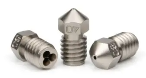
That’s what they look like. See that nifty little pattern on the back there? That’s 3 separate holes drilled at an angle creating significantly more surface area inside the nozzle. That surface area comes into contact with the filament as it enters the nozzle transfer in heat in that much more area. That one change nearly doubles the volume. Well what’s that got to do with what we’re building.
Well it’s simple. We’re getting a standard length Diamondback leaving all that vacant space in the heater block for whatever we want. I haven’t decided exactly how I want to go about this but I do know exactly what I want the finished product to be. We’re going to take a piece copper (either M6 copper rod or straight copper rod turned down to extremely tight clearance on the lathe) and take up the remaining space in the heater block. This copper is going to have 3 holes drilled through it similar to the CHT nozzle. Will abrasive filament wallow out the inside of the copper tube? Probably. We’ll deal with that when we get there.
This will give us the massive surface area of the CHT times the length of the super volcano plus the Diamondback nozzle’s thermal conductivity plus running probably 100 degrees hotter than a typical nozzle all resulting in a hot end that can burn through an entire roll of filament in minutes.
Has anyone done a 10 second benchy yet?
Other Considerations
One other issue that’s likely to come up is the heat break. Obviously an air cooled heat break won’t work inside an oven. But guess what. Water cooled heat breaks do exist and we have one. If you refer back to the picture you can see a radiator with a tub and pump and lines running to our fancy water cooled heat break. Additionally all of our lines and wires that go to the carriage will be insulated inside a ceramic flexible conduit. I’m debating adding some sort of manifold at the carriage and a return conduit line so I can pipe cool air through the conduit just to be extra safe. It’s impossible to find “high temp” versions of a lot of this stuff.
One thing I left out with the giant motors is the transfer of torque. Like any drag racer will tell you all the power in the world is meaningless without traction. For this I’ve got some 9mm wide, fiber backed, GT2 timing belt. They make 12mm but it’s pretty tough to find which means the price is insane. I also found some high temp Gates GT2 belt which is absurdly priced as well. I ordered about $30 worth of it and got about 5cm. When I argued they gave me the wrong length they fired right back that they didn’t and were pretty nasty about it so forget that. Hopefully the stuff I got will hold up. I know it would be fine at room temp but I worry it will soften at 100C.
What else, what else…
Oh yeah, actual power, as in electricity. I’m using a monster power supply, at least in terms of 3D printers. 60V 10A. You can see the voltage regulator boards sitting on it on the printer bed. Max voltage on the TMC5160s is 35 so we’ll trim it down with those but we’ll have loads of current to spare.
I also got a fat driver for the bed/chamber heater but there’s still some debate here. I’m considering using 120v so it doesn’t take an hour to heat up but that of course comes with its own dangers. 60v should heat it up ok and when it’s coming up to temp there should be no other load so close to the full 10 amps. Dunno, this may require experimentation. Affixing the heating element is another question. I’m considering just plain old nichrome wire with a silicone pad to insulate it but I’m undecided. I’d rather not buy another heavy duty BJT to regulate current how ever. I guess this would have to max at 15 amps 120v unlike the 40amp BJT for the smelter project.
Concussion I mean Conclusion
As you can see there’s miles to go on this project however I could have this printing PLA or PETG probably tomorrow if I got to it. I need to finish machining the plates for the X/Y driveshaft idler mounts. Hmm, I could throw a standard E3D with the standard Super Volcano hotend and nozzle. I guess I still need to machine out plates for the Z axis motors. I think that’s just about it. Tempting… The dust collector project still has about 60 hours of printing on the Tevo to go and it’s starting to sound funny. Have to see about all that.
Subscribe below so you don’t miss the next project update and check out my other articles, you may not find them interesting but I do.
See ya!
UPDATE!
I was doing a little research and found out Marlin has added Input Shaping or what I called resonance mitigation or harmonics damping. So we’re going with Marlin and all our fancy BIGTREETECH hardware.