
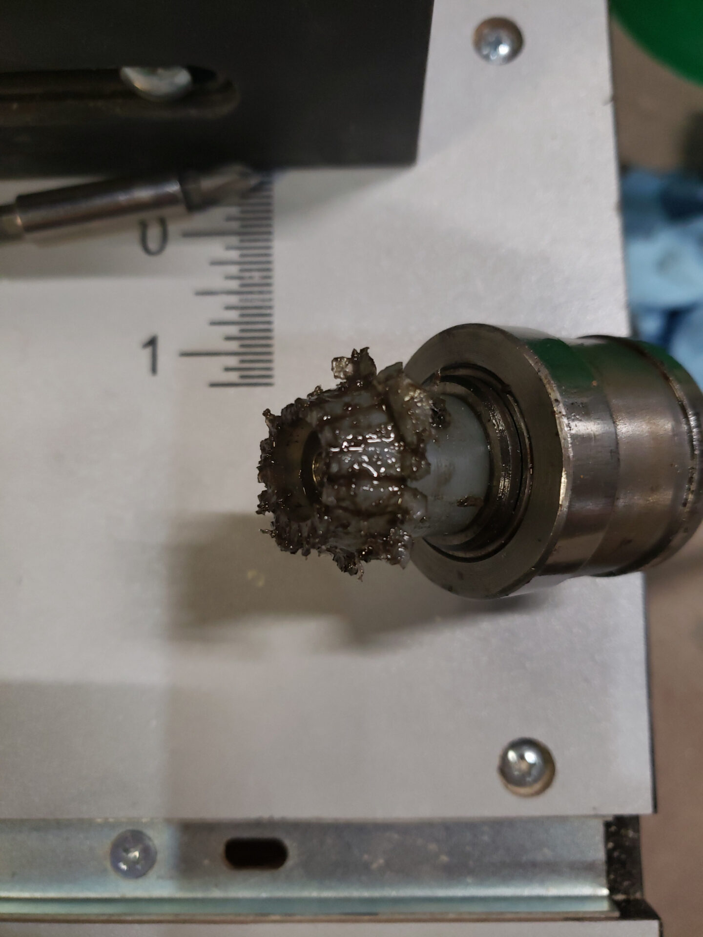
As they say, mistakes were made. That used to be a gear. Specifically the gear that tied the handwheel to the lead screw that moved the spindle up and down in my surface grinder.
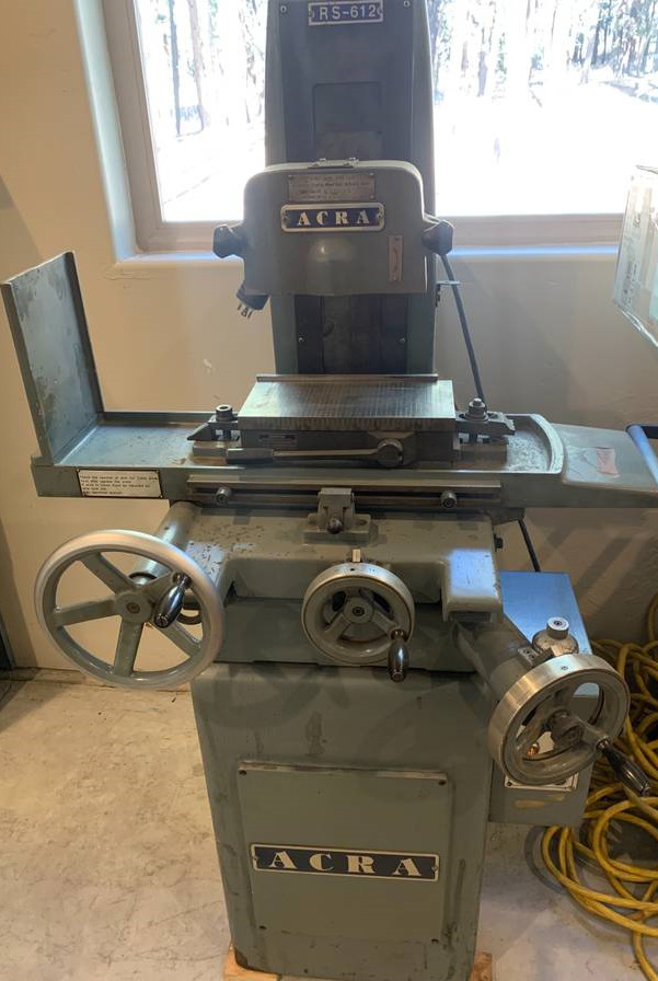
I picked this surface grinder up for $500 somewhat recently. If you aren’t familiar with this kind of machine the function is pretty simple. The bed moves left and right, the plate in the middle of the bed is magnetic, that’s where your part goes, and the thing that says ACRA on it has a grinding wheel inside. You turn the crank on the lower right to lower the grinding wheel into your part and run your part left and right, in and out, and it flattens the surface of the part out, hence surface grinder. The important part is that part is then flat to within 0.0001 inch.
What had happened was…
These are typically expensive machines, high 4 digit to low 5 digits. As you can probably guess, a 3 digit price tag means there’s issues. That’s where the gear from the intro comes in.
This machine has a constant oil flow to all the surfaces that slide on each other. See when you get into these kind of tolerances you basically need big metal surfaces clamped on other metal surfaces with a tiny layer of oil between them so they can slide on each other, sliding surfaces for future reference.
For some unknown reason (probably because they got tired of cleaning up the mess) someone had disconnected the oil pump on this machine, both electrically and mechanically. As far as I can tell they then decided to keep using it. Unfortunately when you have to metal surfaces (cast iron in this case) rubbing against each other constantly the end result is heavy wear.
SEO suggests a new heading here
And boy had they achieved some wear. Unfortunately so much wear that trying to move the spindle to the lower inch or two of travel caused it to bind completely due to it needing to be clamped so tightly in the higher range of travel where the sliding surfaces were heavily ground away.
Turns out the gear that controls that vertical travel happens to be made of plastic. Seems like a real bad idea to me. Unfortunately I didn’t know this at first. In order to make sure the part is perfectly perpendicular to the spindle column you have to grind the top of the magnetic chuck with the machine any time you remove it, which I did to clean everything up.
When I attempted to lower the spindle down to the chuck it started to get a little more difficult to turn the crank. Now in my defense I certainly didn’t go whole hog on this handwheel or anything but I did give it a little force and then without even a small sound the wheel slipped and started turning completely freely. I didn’t know what happened at first. After finally tearing the machine down completely I found the gear…
The Fix
So what the heck do we do now. Well this gear needs to be replaced of course. However in order to replace this gear we need to do some forensic science to determine what the gear even was and I’m afraid we don’t have a ton to go on.
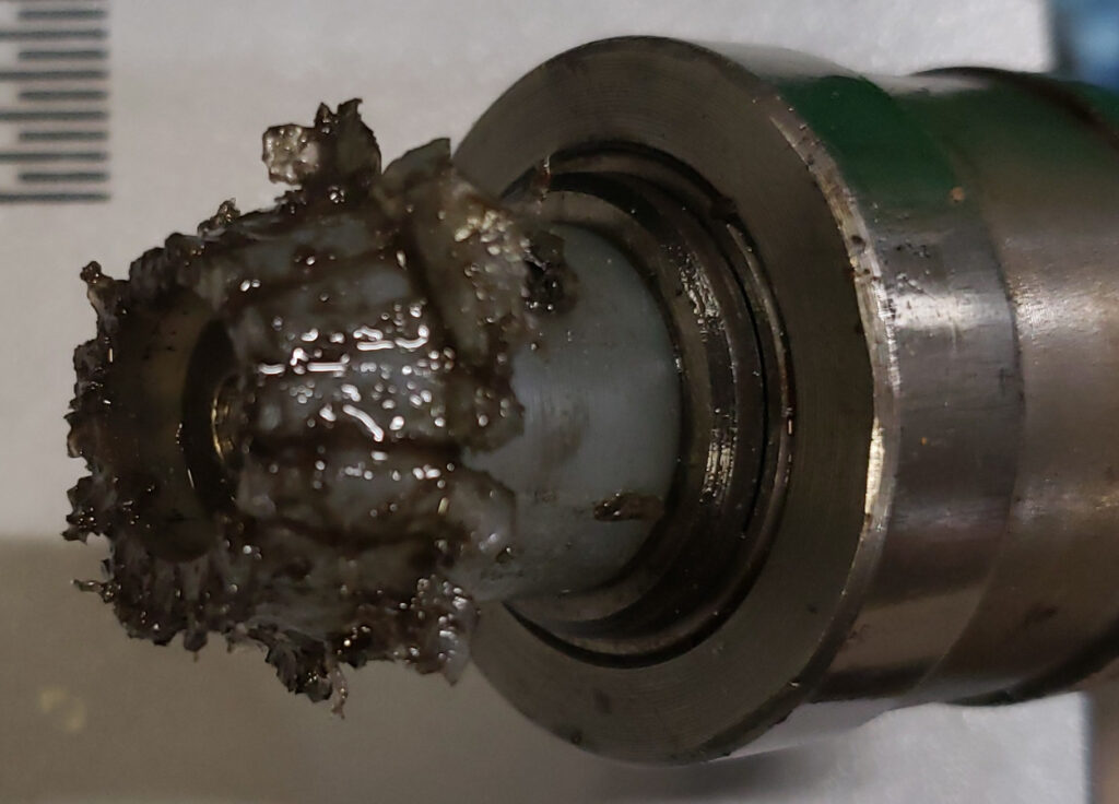
After cleaning it up a bit and studying it I can tell you there was 15 teeth (counting is hard, foreshadowing). Putting a protractor on it tells me the teeth gullet ran at approximately 70 degrees. The shaft is roughly 12mm. The exterior of the front of the gear teeth was about 17mm and the tail something like 23mm. Unfortunately bevel gears are extremely complicated. There’s all those measurements plus a bunch more I don’t have a good way to decipher.
Furthermore, I can’t find a 15 tooth bevel gear anywhere near this size anywhere. Wonderful, this is a complete oddball.
So what do we do in a situation like this? Well we wing it of course.
Winging it
The good news is this gear will probably never exceed 1 RPM. It interfaces with a bronze gear which is part of a collar that rides on a lead screw which is bound by the spindle carriage. When the gear turns the collar turns and the lead screw, which can’t turn, climbs up or down.
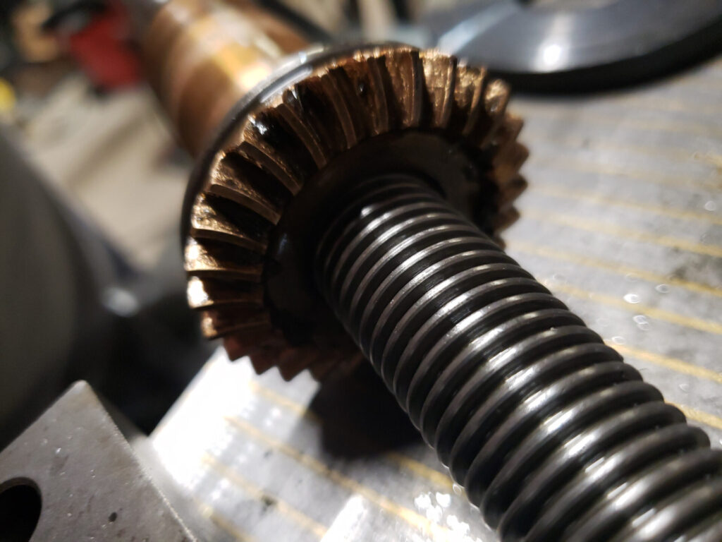
Oh look, spoilers for later, those teeth are also curved. I didn’t notice that at this point, bet that won’t be a headache down the road. I have a CNC router but I don’t have a forth axis so I have no way to make a compound bevel gear or whatever the correct name is for this thing. Guess that explains why this ruined gear was made of plastic. Any other manufacturing process would have cost a fortune.
Gearing Up
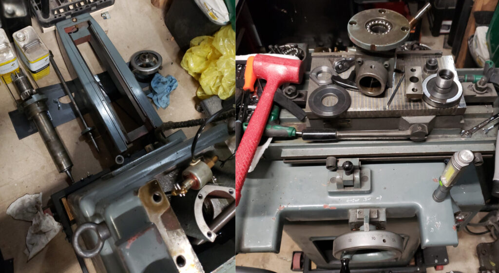
I don’t think I’ve introduced everyone to my shop yet, just a couple small glimpses here and there. Get ready for a narrow window into the rest of the machines, or at least some of them.
So with our rough measurements we can start making something, maybe eventually a gear but lets not get ahead of ourselves. See it’s worth noting, I’ve never done this before and I have no direction other than my handy dandy Machinery’s Handbook.
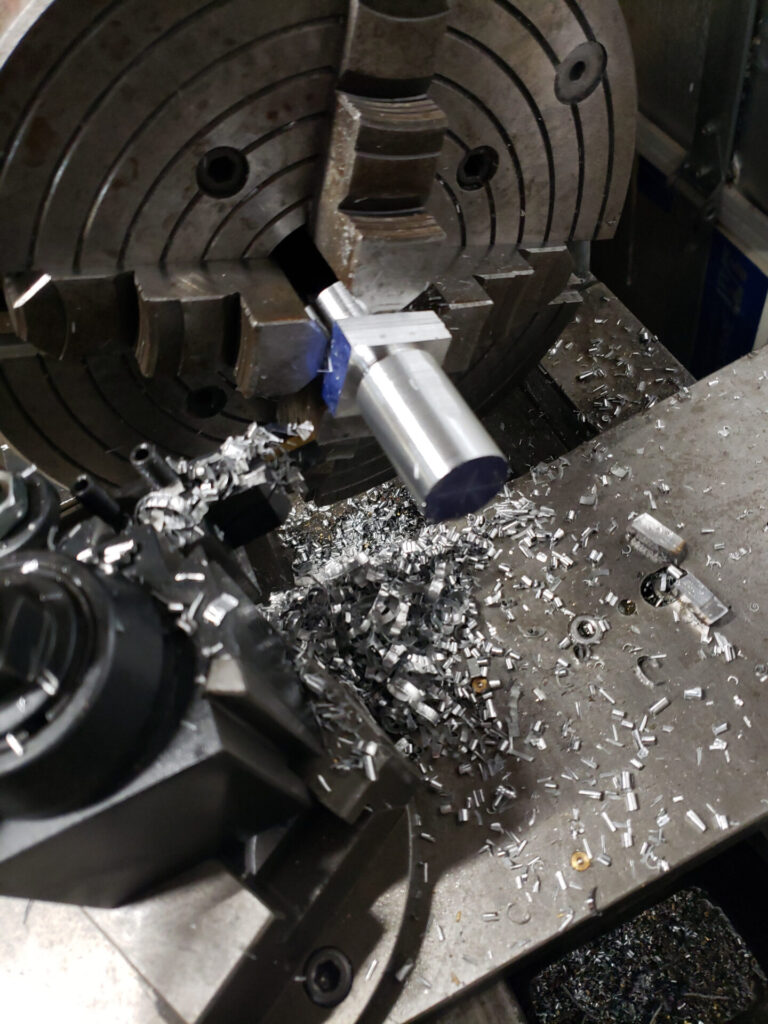
So first we need a gear blank. I’m going to make this out of 6061 aluminum. It may not be the ideal material but I have some laying around and it’s easy to work with plus if a plastic gear held up this should do fine. I don’t have any round stock either so I chopped off a little piece of bar stock on the handy giant bandsaw.
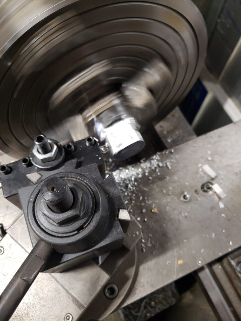
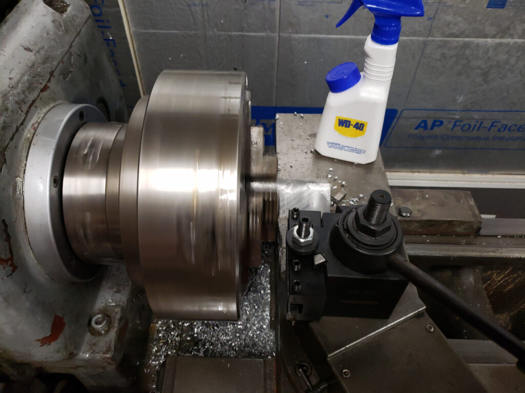
Everyone, meet the lathe, lathe, everyone. Of course thanks to the square stock the next thing I got to do was change over to the four jaw chuck. Those chucks must weigh 80 lbs. Can’t wait to get that electric winch gantry system installed. Anyway, cut the stock down to round stock.
If you look close you might notice a couple broken pieces of HSS tooling. I definitely didn’t try to cut corners and mount this square stock in a three jaw chuck first and you should definitely never do that as well.
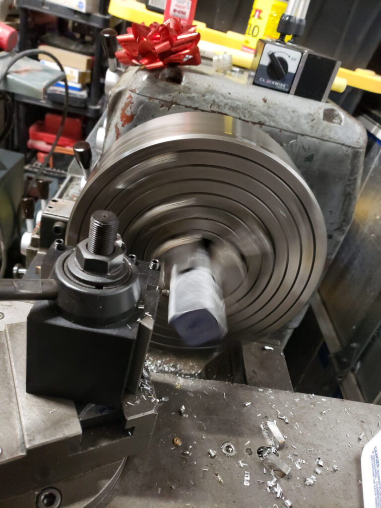
Hey, that’s pretty good!
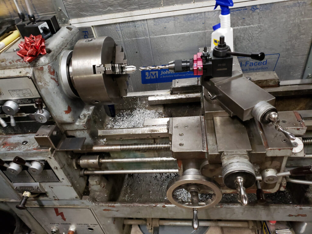
I guess I didn’t get a shot of using the compound slide to taper the end of the piece but I did that (after another chuck change, ugh). And now it’s time to drill the 12mm hole through the part. I got that tool post drill chuck from Edge Technology, it’s pretty great. This lathe didn’t come with a tail stock. How you manage to lose a 100+ lbs cast iron tailstock, I don’t know, but they did apparently. I’m working on building a new one. I’ll probably post that once it’s done as well.
Enter the Milling Machine
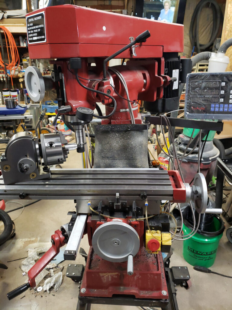
Is this a Harbor Freight milling machine? Yes. Is it any good? You bet it is, after some serious upgrading including a DRO, one shot oiler system, and as with all machining equipment a full teardown, cleaning, and deburring, as well as a lot of testing for accuracy and all that.
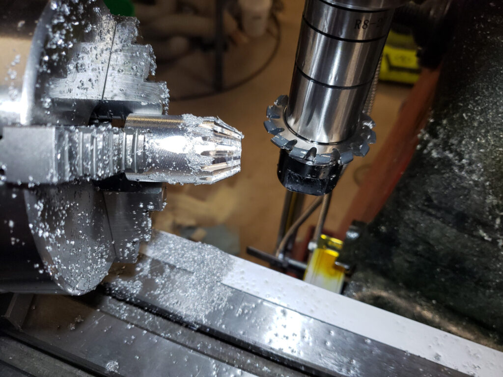
So now we need to cut the teeth. The mill doesn’t have enough depth to position this straight on so I had to spin the turret a good distance to get to the back of the gear blank. Don’t mind RLM learning about manners in the background there.
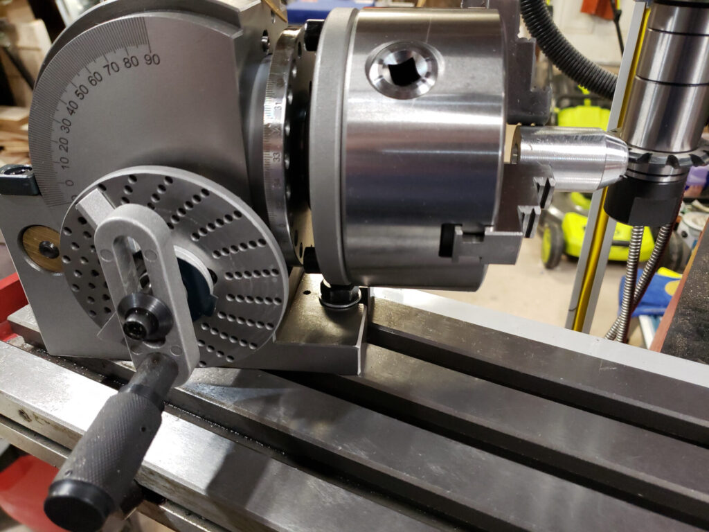
This is a dividing head. The perfect tool for cutting gears on a milling machine. I can do some other stuff too. So the dividing head is mounted at 70 degrees off the spindle since we only have straight directions of travel.
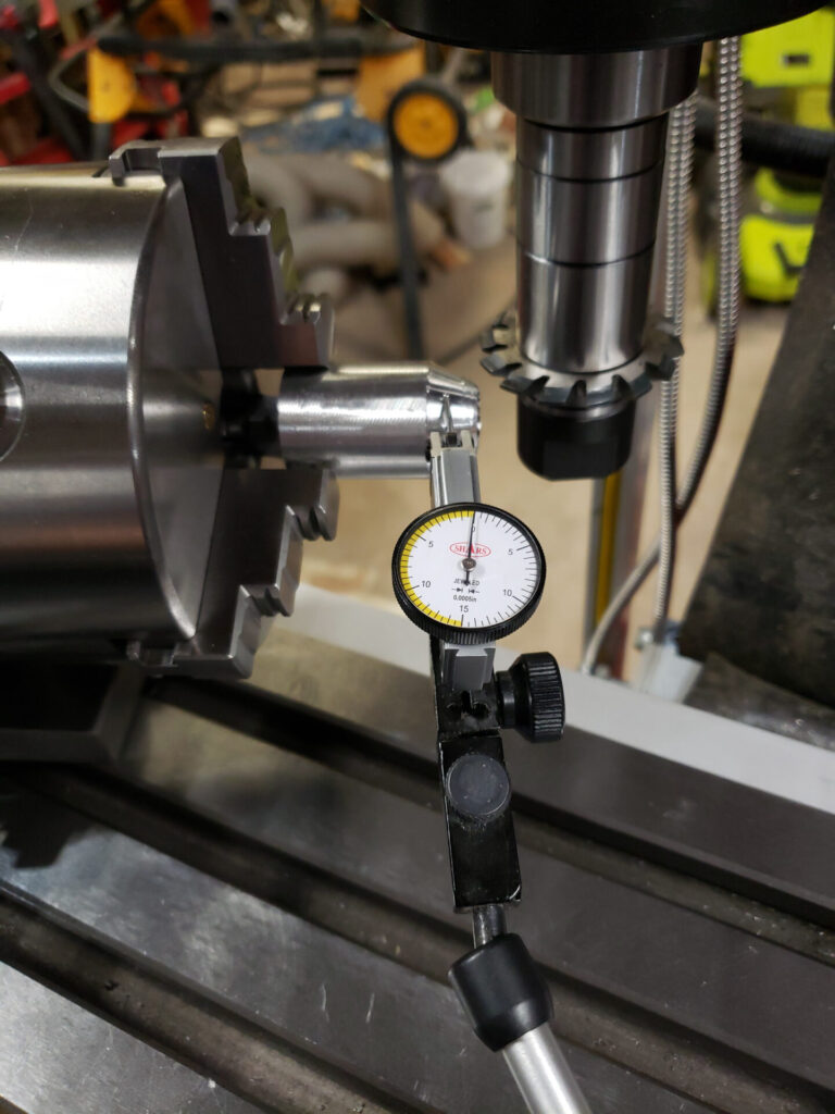
And we want to indicat this in to make sure the blank is running true.
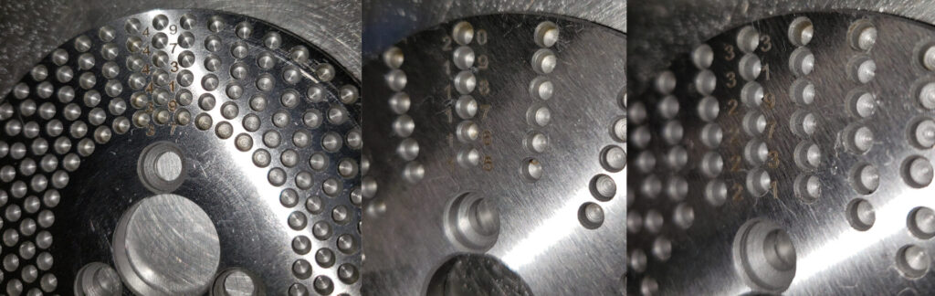
Now this gets a bit complicated. These plates are used to divide the rotation of dividing head into specific increments. The dividing head chuck turn 1 time for every 40 revolutions of the hand crank. That means each crank revolution is 9 degrees. We need 15 teeth so that means each tooth is 24 degrees past the last. That means we need to turn the crank 2.66 repeating times for each cut. 0.66 is 2/3 so we use the plate that’s divided into 15 segments. For each tooth we turn the crank 2 full revolutions plus 10 of the 15 holes for 2/3 or 0.66 of a full rotations. Kinda sorta simple, right?
And that took forever. But it worked!
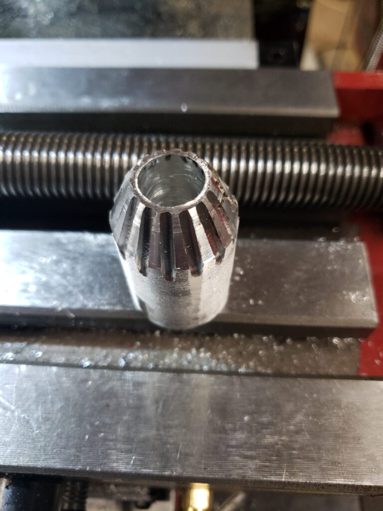
Look at that! Kind of a finished product, right?
Finished?
Well that was all just practice. Yep that’s what I intended all along. Just a practice run preparing for the real thing. Good thing we practiced as well because that gear never would have worked. Turns out there should be 14 teeth for starters. See it was always supposed to be 14 teeth. Somehow I got it into my head that 15 gullets would result in 14 teeth. Guess what? That’s incorrect. Want 14 teeth? Cut 14 gullets.
You may have also noticed those teeth are not really very well or completely formed. Even if the count was right I doubt this would work.
Take 2 – For real this time
As you can probably tell, this blank looks much much better.
Hey look! They actually look like gear teeth this time.
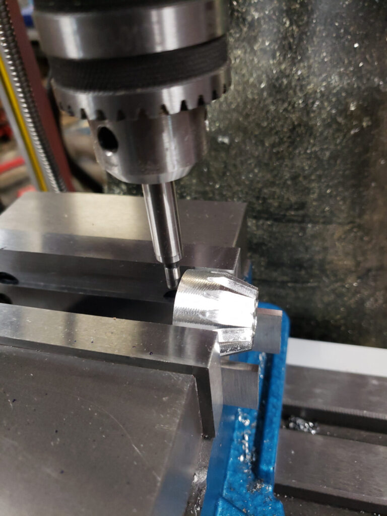
Don’t worry, I’m just locating so I can make sure I drill the roll pin hole in the center and the correct distance from the base. Any lateral force would have sent this fly across the room with this minimal hold. Speaking of I missed a step, I parted this to the correct length back on the lathe with barely and bite on the part, didn’t care for that.
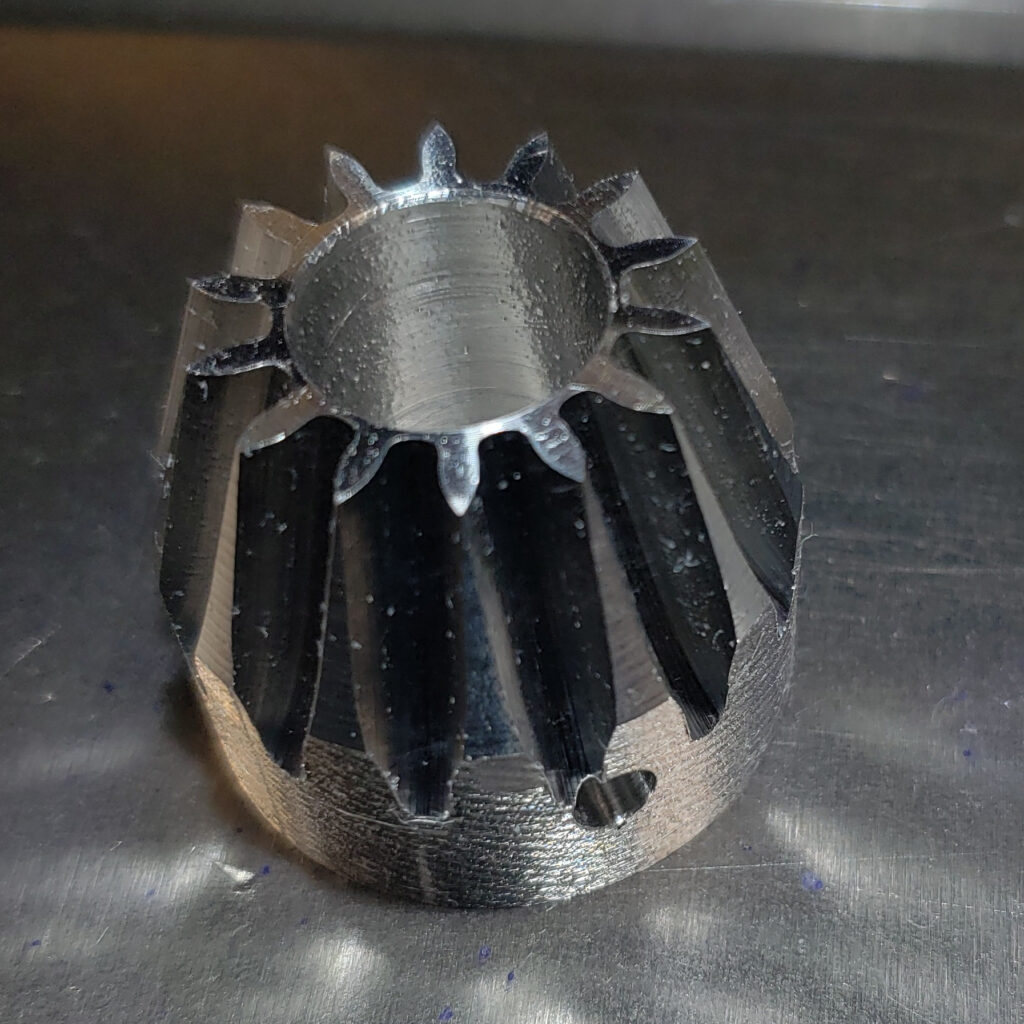
And there it is, all done!
Re-assembly, again
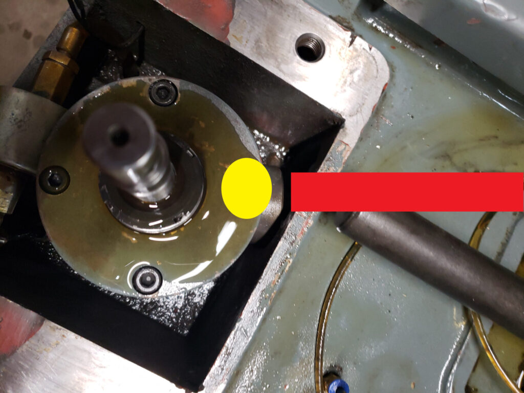
Here’s just a bit of reference info for clarity. This is a top down view of where the column goes. The yellow circle is where our new gear goes with the shaft that connects to it where the red box is. The bronze gear it interfaces with is under the top plate.
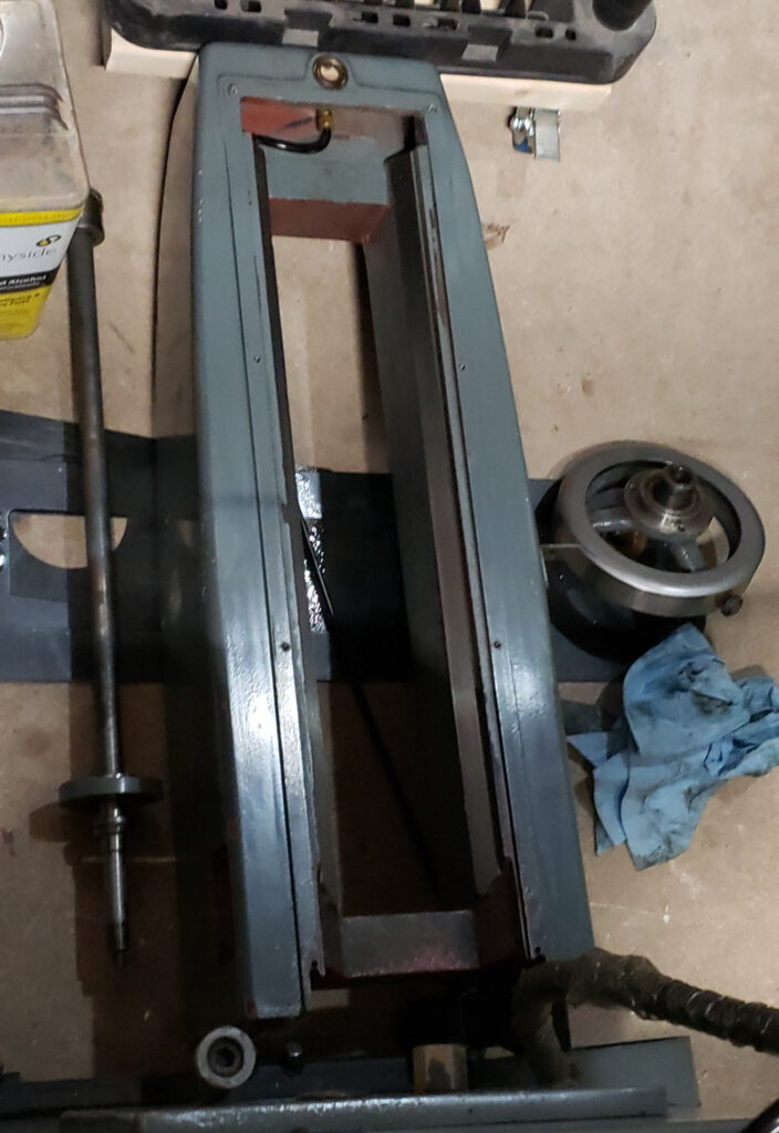
Then the column goes on. I tell you what. After 3 or 4 rounds of removing and installing that column I’m tired of picking it up. That’s about 3 feet tall and is cast iron. It weighs somewhere between 150 and 200 lbs. Have I mentioned I’m old? Well I’m old. And no, I don’t have an assistant. Can’t wait until my electric winch gantry system is installed…
Finale, Finally?
So after all that does it work? You bet your ass it does. Works perfectly! You may wonder how I got that straight bevel gear to mesh with that curved tooth other bevel gear. Well simply put I cheated. I took a triangular file and straightened out the teeth a bit. Considering the minimal pressure, the extreme low speed, and the functional equivalent of a worm gear by way of the lead screw I believe it will be fine. Would I recommend someone else do this? No, not really. Also it seems like this might actually be a spiral miter gear rather than a bevel gear. It’s definitely supposed to be a spiral whatever either way.
Unfortunately this machine is a can of worms and I still can’t get a flat part out of it but I have a solution. Subscribe so you don’t miss that article when I get to part 2. Thanks for reading!